Handover properties dialog box
This topic describes the purpose of the Handover properties dialog box and all the settings and buttons on it.
This feature requires option E7 Advanced CDRs. If you do not have this option this dialog box is not available.
The Handover properties dialog box allows you to edit how an individual handover sector, selected using the HO data tab, is displayed on the map. Note, this dialog box does not change how the sector, selected using the CDR data tab, is displayed on the map, that is set using the Sector information dialog box.
Editing the appearance of a handover sector is not something that is required often. However, you may want to edit it if the azimuth was not provided in the CDR file, or to help with the visualization of the handover sector on the map.
For further information refer to Using handover data.
NOTE: Handover data is only provided in the ATT CDR file format.
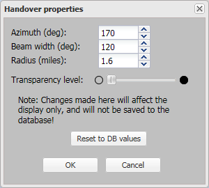
Select an alternative value to change how the handover sector's azimuth is displayed on the map. The azimuth is the direction of the handover sector's beam. For example an azimuth of 0 degrees means the beam's center is directly North; and an azimuth of 90 degrees means the beam's center is directly East. The available range is 0 to 359 degrees.
The default azimuth value used for each handover sector is that which is included in the CDR file. Any change you make is saved and is used to display the handover sector on the map. However it is not updated in the database therefore if you want to return the azimuth to the value in the CDR file click Reset to DB values. Note, if the azimuth is not detailed in the CDR file then the handover sector is displayed on the map as a complete circle since the orientation is not known. It is also displayed with the radius of the circle 70% smaller that the radius used by default for a normal handover sector.
Select an alternative value to change how the handover sector's beam is displayed on the map. The available range is 1 to 360 degrees.
The default beam width value used for each handover sector is that which is included in the CDR file. Any change you make is saved and is used to display the handover sector on the map. However it is not updated in the database therefore if you want to return the beam width to the value in the CDR file click Reset to DB values. Note, if the beam width is not detailed in the CDR file then the value specified in Input and settings view is used.
Select an alternative value to change how the handover sector's radius is displayed on the map. The available range is 0.1 to 30 miles. Any change you make is saved and is used to display the handover sector on the map.
The default radius value used for each handover sector is 80% of the value specified in Input and settings view. This is simply to make it easy for you to distinguish between the handover sectors and sectors from the cell tower data as frequently these overlap each other.
Use the slider to change the transparency of the selected handover sector. Reducing the transparency level is useful if you have multiple items displayed on the map that are overlapping each other as it makes it easier to read the underlying map layers and street names.
Click to reset the azimuth and beam width to the values in the CDR file, and the radius to 80% of the value specified in Input and settings view.
Click to apply any changes you have made. The dialog box closes automatically.
Click to close the dialog box without applying any changes you may have made.