Using call locations calculated from triangulated data
This topic describes how to use the estimated call locations calculated from triangulated data to help identify the possible location of calls. It also explains how to set the appearance of the estimated call locations on the map.
This feature requires option E7 Advanced CDRs. If you do not have this option this feature is not available.
NOTE: Estimated call locations are only provided in certain CDR operator formats. For details of which operators supply this information, refer to table in Analyzing call locations using advanced CDRs.
The following steps describe how to display the estimated call location on the map.
- Open the ESPA analysis center screen and set up the case data as normal as described in Getting started with investigating case data visually.
- Ensure the Advanced dialog box's Advanced CDRs tab has both Use TA/Handovers/Call Locations and Show call locations on map selected.
-
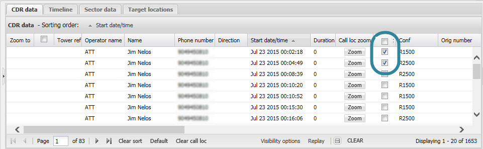
For calls that have estimated call locations, a checkbox is displayed in the call location checkbox column on the CDR data tab.
The confidence level of the estimated call location can be provided either as a specific distance in meters or as a level such as low, medium or high. You can determine what your CDR file provides by viewing the Conf column on the CDR data tab.
 For example:
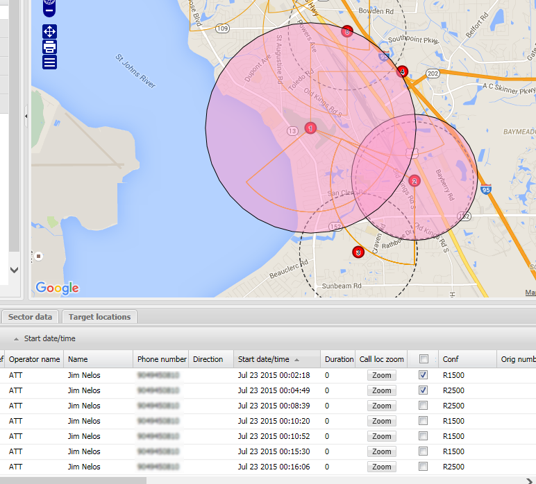
-
This graphic shows two estimated call locations one with a confidence level specified with a radius of 1500m and the other with a radius of 2500m.
-
This graphic shows two estimated call locations one with a confidence level of L (low) and the other of H (high). The color used for these levels and the radius are defined using Call locations with non-specified confidence level distance on the Advanced options dialog box.
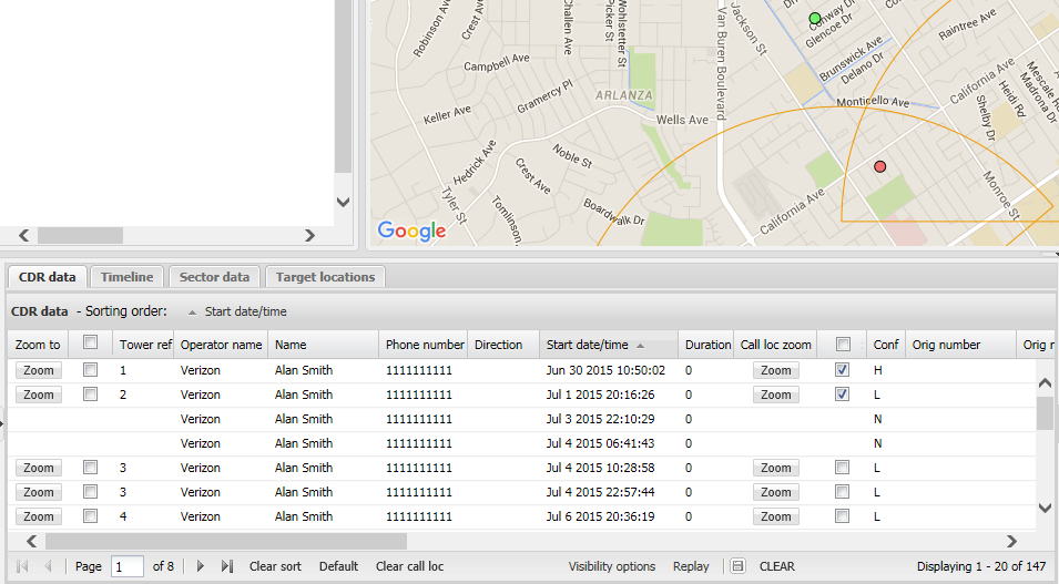
If you want to change the radius used to represent the low, medium and high confidence levels refer to How to set the default radius of estimated call locations which have confidence levels of low, medium and high.
Select the checkbox to display the estimated location on the map.
A circle is positioned on the map displaying the most likely location of the call. The color and size of the circle is dependent on whether the call location is detailed in the CDR file with a specified radius or a confidence level. For call locations with:
- a specified radius, the color of the call location is the same as that which you have selected for the phone number and the size of the circle is dependent on the radius specified in the CDR file.
- a low, medium or high confidence level, the color and size of the call location is that specified in Call locations with non-specified confidence level distance on the Advanced options dialog box.
-
-
To help identify the possible call location further:
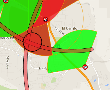
- If you have other calls that are close in time to the one of interest you should display their estimated call location too. This can help define the location further as you may get an overlap with multiple circles.
-
If you also have TA data for the call you can display the TA arc for the call too. This can help define the location further as you may get an overlap of the estimated call location circle with one or more of the TA arcs. To display any associated TA arcs, on the CDR data tab or the Timeline tab select the call you are interested in. Note, to select the call click it and it will highlight in gray, then use the TA data tab to display the TA arc on the map. For further information refer to How to display TA arcs on the map.
The following procedure details how to change the radius used to display an individual estimated call location on the map for CDR files which provide confidence levels as a low, medium or high. This procedure is not applicable if the CDR file provides the confidence levels as a specific distance in meters. This setting overrides the default radius specified using Call locations with non-specified confidence level distance on the Advanced options dialog box.
-
Right-click the estimated call location on the map and select Call location properties ....
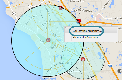
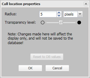
The Call location properties dialog box opens.
-
Set the radius as required then click OK. This setting is then immediately applied on the map to the selected estimated call location.
For further information refer to the Call location properties dialog box.
The following procedure details how to change the default radius and the measurement units used to display estimated call locations on the map for CDR files which provide confidence levels as a low, medium or high. This procedure is not applicable if the CDR file provides the confidence levels as a specific distance in meters. Typically you will not change the radius setting, however it may be useful to set it larger than the default if you are zoomed-out of the map and you want to make the call locations more visible.
You can determine what your CDR file provides for the confidence levels by viewing the Conf column on the CDR data tab as shown in the following graphic:

NOTE: This procedure does not apply to estimated call locations which you have set an individual property on using the Call location properties dialog box.
-
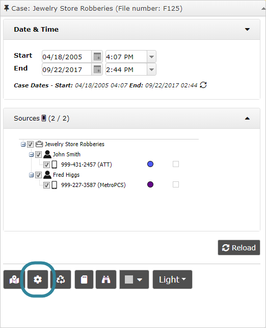
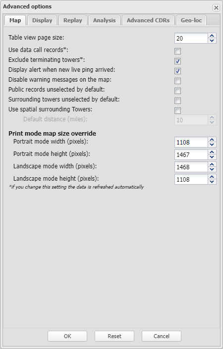
On the ESPA analysis center, open the Advanced options dialog box.
You can open the Advanced options dialog box from either the Input and settings view or the Map view.
- On the Input and settings view:
Click
 .
.
-
On the Map view:
- Hover over
 on the top-right of the map.
 -
Click
 then select Advanced options from the menu.
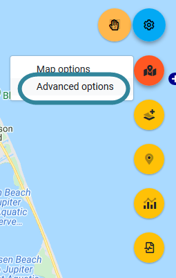
- Hover over
The Advanced options dialog box opens.
- On the Input and settings view:
-
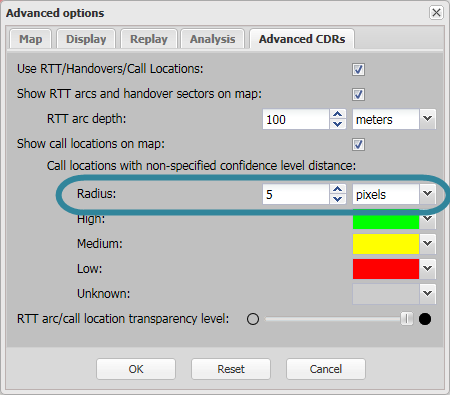
Select the Advanced CDRs tab.
-
Use Radius and select your preferred units to edit the default radius of the estimated call locations then click OK.
For call locations with confidence levels of low, medium and high, this setting is then immediately applied to all that are currently displayed and any new ones that you select to display.
For further information refer to the Advanced options dialog box.
The following procedure details how to change the default color used to display estimated call locations on the map for CDR files which provide confidence levels as a low, medium or high. This procedure is not applicable if the CDR file provides the confidence levels as a specific distance in meters.
You can determine what your CDR file provides for the confidence levels by viewing the Conf column on the CDR data tab as shown in the following graphic:
-
On the ESPA analysis center, open the Advanced options dialog box.
You can open the Advanced options dialog box from either the Input and settings view or the Map view.
- On the Input and settings view:
Click
.
-
On the Map view:
- Hover over on the top-right of the map.
-
Click
then select Advanced options from the menu.
- Hover over
The Advanced options dialog box opens.
- On the Input and settings view:
-
Select the Advanced CDRs tab.
-
Use the Low, Medium, High and Unknown color settings under Call Locations with non-specified confidence level distance to select the colors.

For call locations with confidence levels of low, medium and high, these settings are then immediately applied to all that are currently displayed and any new ones that you select to display.
For further information refer to the Advanced options dialog box.
The following procedure details how to change the transparency level for an individual estimated call location, however if you want to change the transparency level for all estimated call locations refer to How to set the default transparency level of all estimated call locations.
-
Right-click the estimated call location on the map and select Call location properties ....
The Call location properties dialog box opens.
-
Set the transparency level as required then click OK. This setting is then immediately applied on the map to the selected estimated call location.
NOTE: If you apply an individual transparency level the actual level displayed is a combination of the default transparency level set using TA arc/call location transparency level and the individual level set in this step. For example if the default setting is set to 50% and the individual setting is set to 50% the overall transparency is displayed as 25%.
For further information refer to the Call location properties dialog box.
The following procedure details how to change the transparency levels of all estimated call locations, however if you want to change the transparency level for an individual estimated call location refer to How to change the transparency level of an individual estimated call location.
-
On the ESPA analysis center, open the Advanced options dialog box.
You can open the Advanced options dialog box from either the Input and settings view or the Map view.
- On the Input and settings view:
Click
.
-
On the Map view:
- Hover over on the top-right of the map.
-
Click
then select Advanced options from the menu.
- Hover over
The Advanced options dialog box opens.
- On the Input and settings view:
-
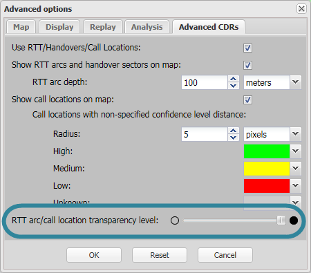
Select the Advanced CDRs tab.
-
Using TA arc/call location transparency level move the slider to the required transparency position than click OK. This setting is then immediately applied to all the estimated call locations that are currently displayed and any new estimated call locations that you select to display.
NOTE: If you have an individual transparency level applied to any call locations then the actual level displayed is a combination of this default transparency level and the individual level set using the Call location properties dialog box. For example if the default setting is set to 50% and the individual setting is set to 50% the overall transparency is displayed as 25%.
For further information refer to the Advanced options dialog box.
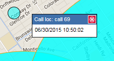
The following procedure details how to display on the map the call ID, and the date and the local time associated with the estimated call location.
-
Right-click the estimated call location on the map and select Show call information.
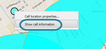
A box opens which provides the call ID, and the date and the local time of the call. The phone number is also displayed if more than one is selected in Sources.
The following procedure details how to disable the estimated call locations layer and the call location checkbox, Call loc zoom and Conf columns on the CDR data tab from displaying. Although this is not common, you may want to do this if you have a lot of advanced CDR data that you currently do not want to analyze. Disabling it will improve the speed performance of the ESPA analysis center screen.
- Open the ESPA analysis center screen and set up the case data as normal as described in Getting started with investigating case data visually.
-
On the ESPA analysis center, open the Advanced options dialog box.
You can open the Advanced options dialog box from either the Input and settings view or the Map view.
- On the Input and settings view:
Click
.
-
On the Map view:
- Hover over on the top-right of the map.
-
Click
then select Advanced options from the menu.
- Hover over
The Advanced options dialog box opens.
- On the Input and settings view:
-
Select the Advanced CDRs tab then unselect Use TA/Handovers/Call Locations then click OK.
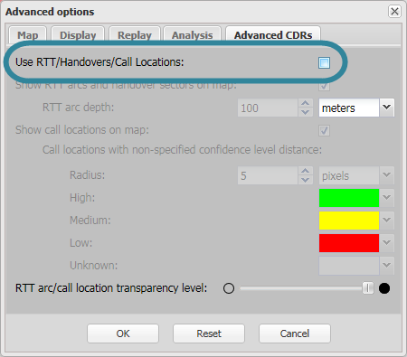
The estimated call locations layer and the call location checkbox, Call loc zoom and Conf columns on the CDR data tab are no longer displayed.
For further information refer to the Advanced options dialog box.