TA arc properties dialog box
This topic describes the purpose of the TA arc properties dialog box and all the settings and buttons on it.
This feature requires option E7 Advanced CDRs. If you do not have this option this dialog box is not available.
The TA arc properties dialog box allows you to edit how an individual TA arc, selected using the TA data tab, is displayed on the map.
Editing the appearance of an TA arc is not something that is required often. However, you may want to edit it to help with the visualization of the TA arc on the map.
For further information refer to Using TA data.
NOTE: Timing advance (TA) files are provided by a number of operators all of who refer to it as TA data with the exception of Verizon who use the term Round-Trip Time (RTT) data. For details of which operators supply this information, refer to table in Analyzing call locations using advanced CDRs.
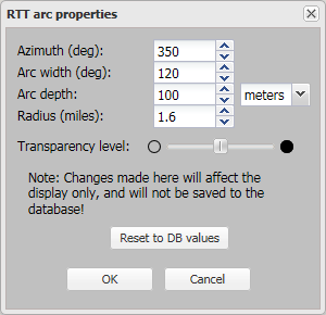
Select an alternative value to change how the TA arc's azimuth is displayed on the map. The azimuth is the direction of the TA arc's beam. For example an azimuth of 0 degrees means the TA arc's center is directly North; and an azimuth of 90 degrees means the TA arc's center is directly East. The available range is 0 to 359 degrees. The default value used for each TA arc is that which is included in the cell tower data file. Any change you make is saved and is used to display the TA arc on the map temporarily, until your browser cache is cleared. However it is not updated in the database therefore if you want to return the azimuth to the value in the cell tower data file click Reset to DB values.
Select an alternative value to change how the TA arc's width is displayed on the map. The available range is 1 to 360 degrees. Any change you make is saved for the specific case you are viewing. The default value used is the value specified in Input and settings view.
Select an alternative value to change how the TA arc's depth is displayed on the map. The default value used is the value specified in TA arc depth.
Select an alternative value to change the distance of the TA arc's radius. The available range is 0.1 to 30 miles. The initial value used for each TA arc is the RTD (round-trip delay) value specified in the CDR file. Any change you make is saved and is used to display the TA arc on the map. However it is not updated in the database therefore if you want to return the radius to the value in the CDR file click Reset to DB values.
Use the slider to change the transparency of the selected TA arc. Reducing the transparency level is useful if you have multiple items displayed on the map that are overlapping each other as it makes it easier to read the underlying map layers and street names. The default value used is the value specified in TA arc/call location transparency level. The actual transparency level used to display the selected TA arc is a combination of the default transparency level and this individual level. For example if the default setting is set to 50% and the individual setting is set to 50% the overall transparency is displayed as 25%.
Click to reset the values using the defaults described in each setting.
Click to apply any changes you have made. The dialog box closes automatically.
Click to close the dialog box without applying any changes you may have made.